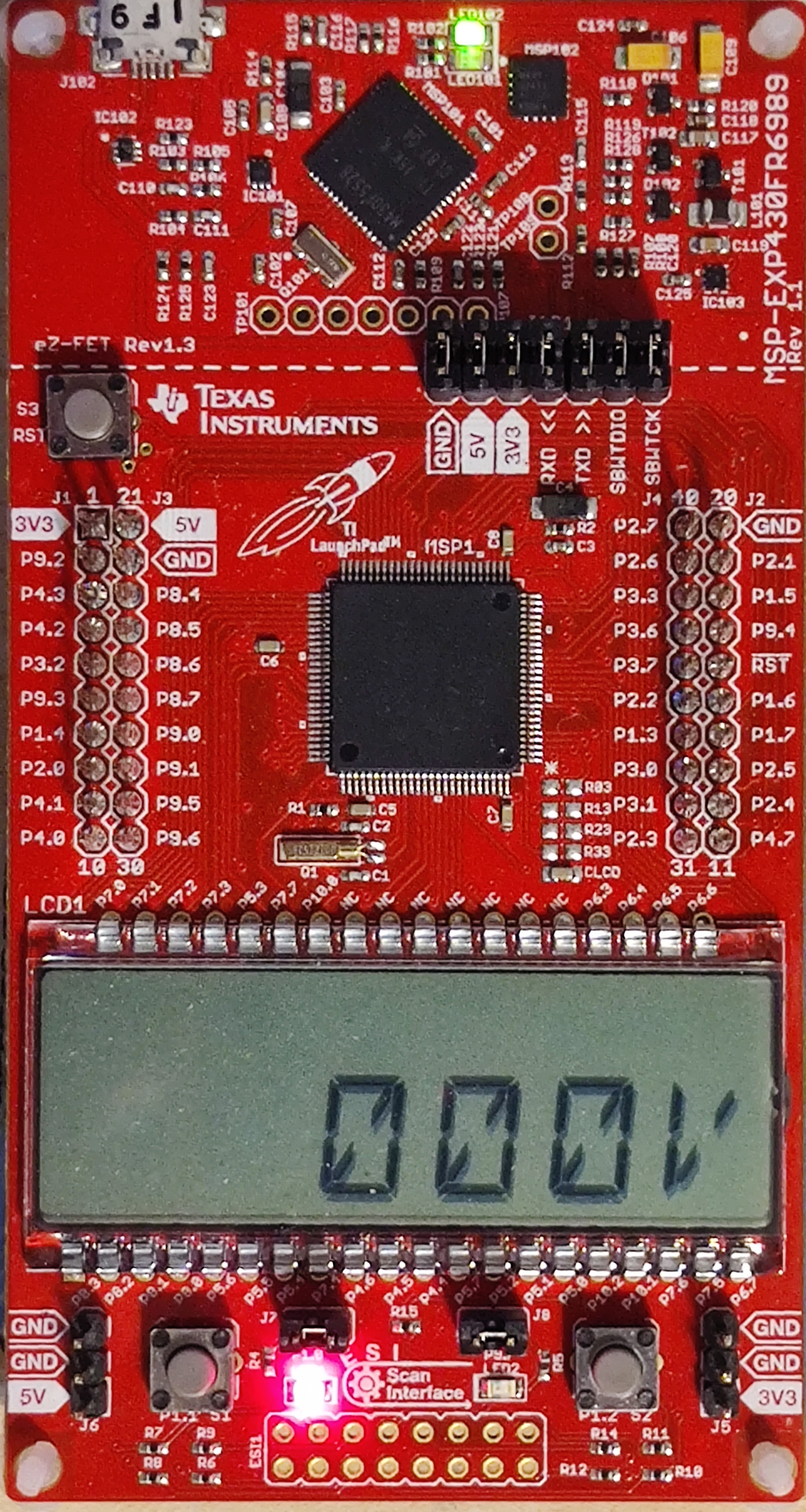
Moppy Player
In my final project for an embedded systems class, I programmed a Texas Instruments MSP430 microcontroller, aimed at operating a multifunctional meter, measuring current and two volt ranges. This project, was designed to integrate various functionalities into a single device showing off the uses of hardware interrupts. My code specifically focuses on interfacing with an LCD display to visualize measurements such as voltage and resistance, with provisions for extending these functionalities through different code sections dedicated to startup, calculation, and display update routines. The challenge of managing simultaneous button and ADC interrupts, demonstrates the intricacies of real-time system programming and hardware interaction.
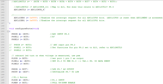
Central to the implementation is the configuration of the MSP430's peripherals, such as ADC (Analog to Digital Converter) for reading sensor inputs, and LCD for output display. The setup routines, including setUpADC() and LCD initialization in main(), are required in the setup to configure device-specific registers and modes for proper operation. This preparation ensures that the microcontroller handles input signals and processes them appropriately, bridging the gap between raw data and user-friendly information. The inclusion of debounced button inputs to cycle through different meter functions allows seamless transition between modes such as voltage measurement and resistance checking without requireing a physical debouncing circuit. Math functions are also required for the processing of the sensor inputs so calc() is also inplemented in the setup. lastly, is the update_lcd() routine so that the processed data can be displayed in a human readable format
This approach not only demonstrates practical applications of embedded software principles, but also shows a clear understanding of hardware-software integration challenges. Each segment of the code, from interrupt service routines to display logic, encapsulates a piece of the broader puzzle in creating a multifunctional embedded system device. The project is a testament to the complexity and rewarding nature of embedded system design, blending theoretical knowledge, low level coding, and practical engineering skills to achieve a tangible and interactive device.
A snippet of the Math and LCD code
void calc(void){
zeroOut();
vHundredths = fmod((Voltage*100),10);
vTenths = fmod((Voltage*10),10);
vOnes = fmod(Voltage,10);
vTens = fmod((Voltage / 10), 10);
vHundreds = fmod((Voltage / 100), 10);
//vThousands = (Voltage / 1000) % 10;
if(vHundreds==0)
{
lcd_num3[0] = 0xfc;
lcd_num3[1] = 0x28;
}else if(vHundreds==1)
{
lcd_num3[0] = 0x60;
lcd_num3[1] = 0x20;
}
if(vTens==0)
{
lcd_num4[0] = 0xfc;
lcd_num4[1] = 0x28;
}else if(vTens==1)
{
lcd_num4[0] = 0x60;
lcd_num4[1] = 0x20;
}else if(vTens==2)
{
lcd_num4[0] = 0xdb;
lcd_num4[1] = 0x00;
}else if(vTens==3)
{
lcd_num4[0] = 0xf3;
lcd_num4[1] = 0x00;
}else if(vTens==4)
{
lcd_num4[0] = 0x67;
lcd_num4[1] = 0x00;
}else if(vTens==5)
{
lcd_num4[0] = 0xb7;
lcd_num4[1] = 0x00;
}else if(vTens==6)
{
lcd_num4[0] = 0xbf;
lcd_num4[1] = 0x00;
}else if(vTens==7)
{
lcd_num4[0] = 0x80;
lcd_num4[1] = 0x30;
}else if(vTens==8)
{
lcd_num4[0] = 0xff;
lcd_num4[1] = 0x00;
}else if(vTens==9)
{
lcd_num4[0] = 0xe7;
lcd_num4[1] = 0x00;
}
if(vOnes==0)
{
lcd_num5[0] = 0xfc;
lcd_num5[1] = 0x28;
}else if(vOnes==1)
{
lcd_num5[0] = 0x60;
lcd_num5[1] = 0x20;
}else if(vOnes==2)
{
lcd_num5[0] = 0xdb;
lcd_num5[1] = 0x00;
}else if(vOnes==3)
{
lcd_num5[0] = 0xf3;
lcd_num5[1] = 0x00;
}else if(vOnes==4)
{
lcd_num5[0] = 0x67;
lcd_num5[1] = 0x00;
}else if(vOnes==5)
{
lcd_num5[0] = 0xb7;
lcd_num5[1] = 0x00;
}else if(vOnes==6)
{
lcd_num5[0] = 0xbf;
lcd_num5[1] = 0x00;
}else if(vOnes==7)
{
lcd_num5[0] = 0x80;
lcd_num5[1] = 0x30;
}else if(vOnes==8)
{
lcd_num5[0] = 0xff;
lcd_num5[1] = 0x00;
}else if(vOnes==9)
{
lcd_num5[0] = 0xe7;
lcd_num5[1] = 0x00;
}
letter();
};
void letter(void){
if(meter_func==4) // 3.3 vMeter
{
lcd_num6[0] = 0x0c;
lcd_num6[1] = 0x28;
}
else if(meter_func==1) { // 25 vMeter
lcd_num6[0] = 0x0c;
lcd_num6[1] = 0x28;
}else if(meter_func==2){ // OhmMeter
lcd_num6[0] = 0x28;
lcd_num6[1] = 0x0a;
} else if (meter_func==3){
// Frequency
lcd_num6[0] = 0x8e;
lcd_num6[1] = 0x00;
}};
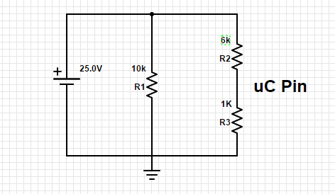
Volt Meter Circuit
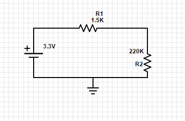
Ohm Meter Circuit
C Code Lines 1 - 26
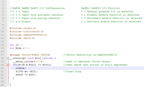
C Code Lines 26 - 49
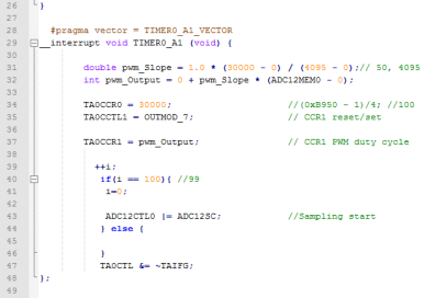
C Code Lines 49 - 79
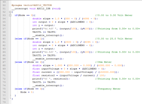
C Code Lines 79 - 109
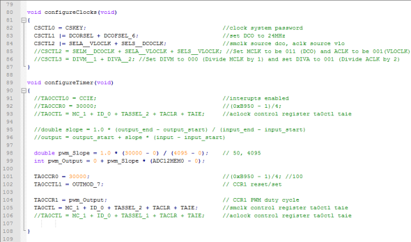
C Code Lines 109 - 139
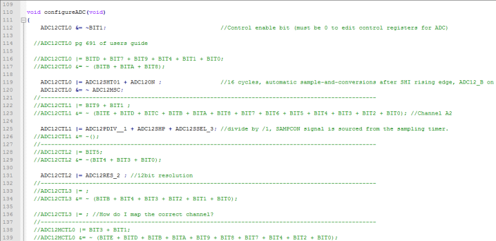
C Code Lines 139 - 169
